C2 PROJECT
C2 Photo Album
album:Easter 2020 - Working from home
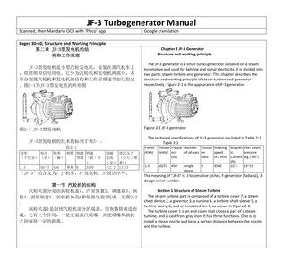
Front cover of the JF-3 turbo generator manual.
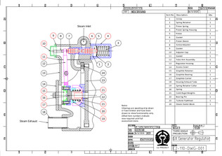
New drawing of the turbo-generator by Erle.
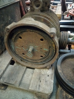
View of the turbine with blades visible round the edge.
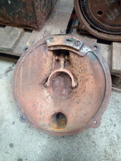
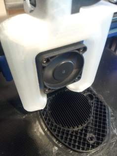
View of inside cover of the turbine. Part of the governor valve gear is visible as well as the exhaust steam pipe outlet at the bottom. At the top, the angled hole can be seen which directs the live steam onto the turbine blades.
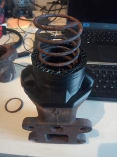
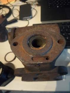
Selection of 3D printed turbo-generator parts and how they fit by Erle, Ed and Tom. Obviously, these need casting for actual use! Thanks go to the Ford family.

Selection of 3D printed turbo-generator parts and how they fit by Erle, Ed and Tom. Obviously, these need casting for actual use! Thanks go to the Ford family.
Selection of 3D printed turbo-generator parts and how they fit by Erle, Ed and Tom. Obviously, these need casting for actual use! Thanks go to the Ford family.
Selection of 3D printed turbo-generator parts and how they fit by Erle, Ed and Tom. Obviously, these need casting for actual use! Thanks go to the Ford family.
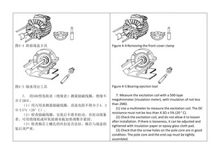
Page 30 of the JF-3 Manual as scanned by Andrew
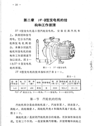
The results of Paul’s efforts. Left is page 30 of the scanned JF-3 manual with OCR software and Right is after translation into English. This book is proving a “gold mine” of information.
JF-3 turbo-generator mounted on a C2 originally built at Harbin in 1960, at Zhanhe Forestry Railway.
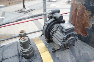
JF-3 mounted on a C2 originally built at Harbin in 1960, and which worked at Zhanhe Forestry Railway:
Dismantling the JF-3
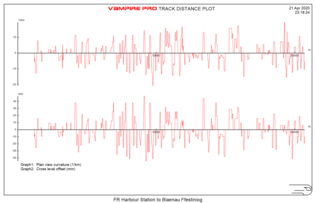
VAMPIRE plots of the FR track design curvature and cant, courtesy of Owen Evans.